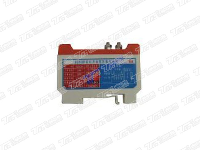
the safety barrier and an instrument supporting requirements:
1, the selected safety barrier and a instrument should be obtained after the national explosion-proof inspection department issued a certificate of explosion-proof and explosion-proof inspection unit after the formation of an intrinsically safe explosion-proof system.
2, cables and a meter are energy storage devices, explosion-proof parameters must be calculated according to the safety barrier, no mistake before being equipped with. (This condition does not take into account the energy of the power).
The basic combination of intrinsically safe explosion-proof system conditions are:
Uo≤Ui
Io≤li
Co≥Ci+C
Lo≥Li+Lo
Uo- highest output voltage
Io- maximum output current
Co- maximum load capacitance
Lo- maximum load inductance
Ui- A meter allows the maximum input voltage
Li- Once the maximum allowable input current meter
Ci- a meter maximum internal equivalent capacitance
Li- a meter maximum internal equivalent inductance
Cp- The maximum allowable distributed capacitance of the conductor (or cable)
Lp- connecting lead (or cable) allows the maximum distribution of inductance
according to national standards for intrinsically safe energy level restrictions:
Ⅱ C grade: 20 µJ
Ⅱ B grade: 60 µJ
When an instrument and safety barrier of the intrinsically safe level is different, the combination of explosion-proof system can only be relegated to use.
the technical specifications and the main parameters
A) Explosion-proof mark: [Ex (ia)] IIC, [Ex (ib)] IIC, [Ex (ib)] IIB
B) Installation location: safe area
C) Installation: DlN standard rail (35mm) installation or bus bar busbar installation; M4 bolt spacing 11.5mm
D) The maximum allowable voltage: 250VAC / DC
E) Environmental conditions: continuous use temperature -10 ℃ ~ +45 ℃; storage temperature -40 ℃ ~ +80 ℃; relative humidity 5 ~ 95% RH
Installation and grounding
A) Installation: Two kinds of installation
1) DlN standard rail (35mm) installation, the safety barrier card directly to the DlN rail.
2) Guide bar installation
A) On a copper bar with a width of 20 mm, drill two horizontal mounting holes 11.5 mm in diameter and ø4.5 mm in diameter. Insert and tighten the two ground studs of the barrier and secure the copper bar to ground.
B) Installation Location: Non-corrosive gas, no strong vibration of the safe place.
C) Terminal number
Non-intrinsically safe terminals: 1,2 intrinsically safe terminals: 3,4
D) The grounding resistance of terminals 5 and 6 should not exceed 4Ω, the grounding resistance should not exceed 1Ω.
Matters needing attention
A) The safety barrier should be installed in a non-hazardous area.
B) The intrinsically safe end of the barrier and the non-intrinsically safe end of the wiring can not be connected wrong, the wires need to be laid separately.
C) It is forbidden to directly test the insulation between safety barrier terminals with megger. If you inspect the system wiring, you must disconnect all the safety barriers.
D) Once the barrier is damaged, the user shall not repair it by himself, it should be replaced.
E) Prohibit the use of zener ground wire for welding and other strong electric operation, so as not to cause a large number of Zener safety barrier burned at the same time
F) When using the secondary instrument, it must be confirmed that the working voltage of all the secondary instruments connected to the safety barrier or its internal voltage may not exceed the maximum value
The maximum allowable voltage of the safety barrier is 250VDC / AC.
G) When the system is intermodulation (no dangerous gas in the scene), disconnect all the barriers of the safety barrier. After confirming the successful commissioning of the system, connect the safety barrier wires and put it into operation.
H) be sure to pay attention to the intrinsically safe circuit wiring and connecting wire restrictions:
1) The intrinsically safe lines and non-intrinsically safe lines shall be laid separately in the busway and protective tube;
2) Intrinsically safe end use blue wire;
3) the insulation strength of the connecting wire should be greater than 500V;
4) The thermocouple lead application compensation wire;
I) Installation, Use and Maintenance of Barriers In addition to comply with this manual, the relevant provisions of GB3836.15-2000 "Electrical apparatus for explosive gas atmospheres Part 15: Electrical installation in hazardous areas (other than coal mines)" must be strictly observed.
Note: Once the Zener barrier is damaged, the user shall not repair and reuse, should be replaced.


 400—756—0186
 Telephone:400-756-0186
 Fax:0377-63235296
 E-mail:yitongex@163.com
 Address:Funiu road eco industrial park, Nanyang City, Henan Province, China